Lennox Hearth T300p User Manual
Browse online or download User Manual for Stoves Lennox Hearth T300p. Lennox Hearth T300P User's Manual
- Page / 40
- Table of contents
- BOOKMARKS
- INSTALLATION AND OPERATION 1
- IMPORTANT WARNINGS 2
- TABLE OF CONTENTS 3
- PLANNING YOUR INSTALLATION 4
- INSTALLATION 10
- CARE AND OPERATION 16
- ROUTINE MAINTENANCE 22
- Face of door 26
- DEFINITIONS 27
- WIRING DIAGRAM 28
- REPLACEMENT PARTS LIST 31
- Page 33 33
- Page 34 34
- OPTIONAL ACCESSORIES 35
- INSTALLATION TIPS 36
- Page 37 37
- 1110 West Taft Avenue 40
- Orange, CA 92865 40
Summary of Contents
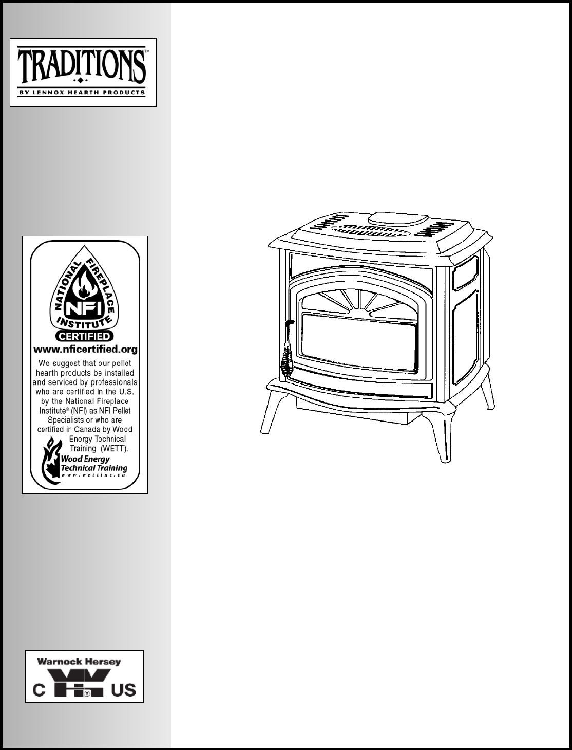
INSTALLATION AND OPERATION MANUAL Frees
INSTALLATION PAGE 10 VENTING REQUIREMENTS It is recommended that only an authorized dealer install your pellet stove. The specified installation requ
INSTALLATION PAGE 11 VENT TERMINATION Do not terminate vent in an enclosed or semi-enclosed area such as: carports, garage, attic, crawl space, under
INSTALLATION Page 12 DETERMINING SIZE OF PIPE TO INSTALL To determine what diameter pipe to use in an installation (3” or 4”), first find the “equiv
INSTALLATION Page 13 INSTALLING YOUR PELLET STOVE Standard Horizontal Exhaust Installation (Direct Vent) 1. Locate the proper position for the list
INSTALLATION INSTALLATION CONFIGURATIONS – Standard Horizontal Installations Note: Horizontal run of pipe requires 1/4” / 7 mm rise per foot. Page 1
INSTALLATION PAGE 15 Installation Configurations / Standard Venting Options This appliance may be connected to an existing flue or by installing lis
CARE AND OPERATION PAGE 16 CONTROL BOARD OPERATION Stove On / Off Button – This button will turn your stove on or off while in Manual or Automat
CARE AND OPERATION Page 17 Note: The control board is equipped with an internal memory which will recall the last setting and mode the stove was in p
CARE AND OPERATION Page 18 Combustion Voltage Trim Steps: 1. Push button “twice” for access voltage calibration mode. 2. Identify the current cali
CARE AND OPERATION Page 19 Manual Operation: Pressing the stove ON / OFF switch initiates the start-up cycle. The green ON / OFF light, near the top
IMPORTANT WARNINGS CAUTION: Read this manual thoroughly before starting installation. For your safety, follow the installation, op-eration and mainte
CARE AND OPERATION Page 20 DAMPER OPERATION The damper is a plate that helps control the amount of airflow supplied for combustion. With the damper
CARE AND OPERATION Page 21 FUEL REQUIREMENTS Using the UltraGrate burn system, this appliance has been designed to burn wood residue pellets with up
ROUTINE MAINTENANCE * Inspect your stove or insert at minimum frequency stated until you establish a minimum frequency required for your installation
ROUTINE MAINTENANCE Page 23 PHOTOEYE The photoeye is positioned to view the flame from the top of the auger feed tube. It is located below the auge
ROUTINE MAINTENANCE Page 24 Clean-Out Tee w/ Cover Removed * (Minimum Frequency of 1-2 months) HEAT EXCHANGER TUBES ONLY CLEAN HEAT EXCHANGE
ROUTINE MAINTENANCE Page 25 DOOR ROPE GASKET The condition of the rope gasket around the door and windows should be checked periodically and replac
SPECIFICATIONS - Model T300P Series Page 26 Flue Size 3” / 76mm Rear Width, Overall 28 3/4” / 730 mm Depth, Overall 26 1/2” / 660 m
DEFINITIONS Page 27 AIR WASH To inhibit buildup of soot on the door glass, air is deliv-ered to the glass through an air wash system located in the d
WIRING DIAGRAM Page 28
TROUBLESHOOTING (Qualified Technicians Only) Unplug Appliance Before Performing Any Troubleshooting or Maintenance Page 29 PROBLEM CAUSE(S) SOLUTIO
TABLE OF CONTENTS Page 3 Important Warnings ... 2 Testing / Listing, EPA, Using this Manual...
TROUBLESHOOTING (Qualified Technicians Only) Unplug Appliance Before Performing Any Troubleshooting or Maintenance Page 30 PROBLEM CAUSE(S) SOLUTION
REPLACEMENT PARTS LIST Page 31 Door Parts & Body Components Item # Part # Description 1 20953002 Door Assembly, Black Painted – Model T300P 1
REPLACEMENT PARTS LIST Page 32 Auger Item # Part # Description 20 12041300 Collar & Screw Set, Auger (3pc.) 21 20950087 End Flange, Auger 22
REPLACEMENT PARTS DIAGRAMS Page 33 1 2 3 4 67810 11 12 5 9
REPLACEMENT PARTS DIAGRAMS Page 34 14 15 16 17 202122 24 25 23 27 13 18
OPTIONAL ACCESSORIES Note: Install and use accessories per instructions provided with the accessory kit. Page 35 Optional AccessoriesItem # Catalo
INSTALLATION TIPS Page 36
SIMPLE OPERATING INSTRUCTIONS LABEL Page 37
T300P PELLET STOVE SAFETY LABEL Page 38 Note that your serial number is printed on the safety label located on the back of the stove. Your stove’s s
Page 39 Dealer’s Name: Dealer’s Address: City: State: Zip Code: Serial Number: Date of Purchase: Date Installed: Notes: SERVICE AND MAINTENANC
PLANNING YOUR INSTALLATION Page 4 QUESTIONS TO ASK LOCAL BUILDING OFFICIAL A correct installation is critical and imperative for reduc-ing fire hazar
1110 West Taft Avenue Orange, CA 92865
PLANNING YOUR INSTALLATION Page 5 FLOOR PROTECTION This appliance requires noncombustible floor protection. If the floor protection is to be stone, t
PLANNING YOUR INSTALLATION Clearances to combustibles are determined from testing to applicable standards for allowable heat transfer. The clearances
INSTALLATION Page 7 MANUFACTURED (MOBILE) HOME INSTALLATION Model –T300P Series In addition to the standard installation instructions, the following
INSTALLATION Page 8 DAMPER ROD INSTALLATION 1. Locate rectangular cutout on bottom stove panel behind ash pan. 2. Screw damper rod into threaded h
INSTALLATION Page 9 THERMOSTAT INSTALLATION: NOTE: Always Disconnect Power Before Perform-ing The Thermostat Installation. A 24-volt wall thermos
Related products and manuals for Stoves Lennox Hearth T300p
 (36 pages)
(28 pages)
(1 pages)
(24 pages)
(1 pages)
(36 pages)
(28 pages)
(1 pages)
(24 pages)
(1 pages)
© 2020, manymanuals.com. All rights reserved. | 0.690 s |
 Manymanuals.com
 Manymanuals.de
 Manymanuals.fr
 Manymanuals.it
 Manymanuals.pl
 Manymanuals.cz
 Manymanuals.es
 Manymanuals-pt.com
Comments to this Manuals